
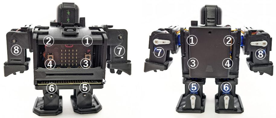
Parts (one arm)
- (x1) Servo(SG90 or MS18)
- (x1) Servo horn on each wing
- (x1) Servo horn on one wing
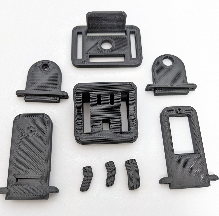
- Arm_Shoulder (above)
- Joint_Servo_A (upper right) (SG90 or MS18. Common partswith legs)
- Joint_Servo_B (upper left) (common parts with legs)
- Arm_Bracket (bottom left and right) (SG90 or MS18)
- Hand (bottom center)
* There is no difference between the right arm and the left arm for printer parts.
Servo horn and bracket preparation
Drilling
This step is not necessary if you can print out with a clean hole.
If the holes in the red circles below are incomplete, clean them with a 2mm pin vise.
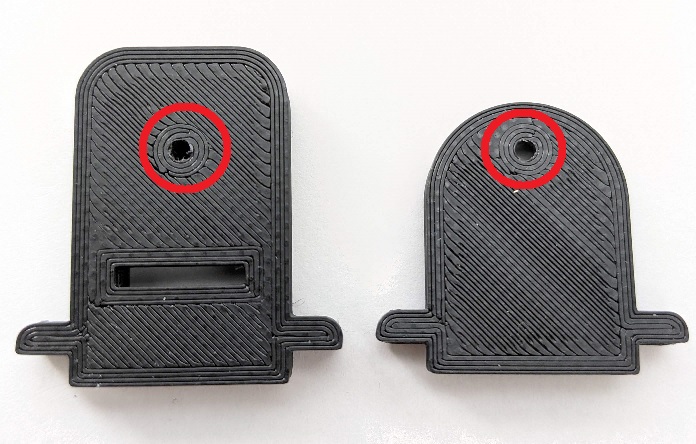
The photo shows the leg parts. The arm is a slightly longer part.
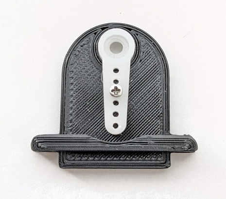
Servo horn installation 1

Use the horns on both wings that come with the servo. (right)
Cut, leaving 4holes. (left)
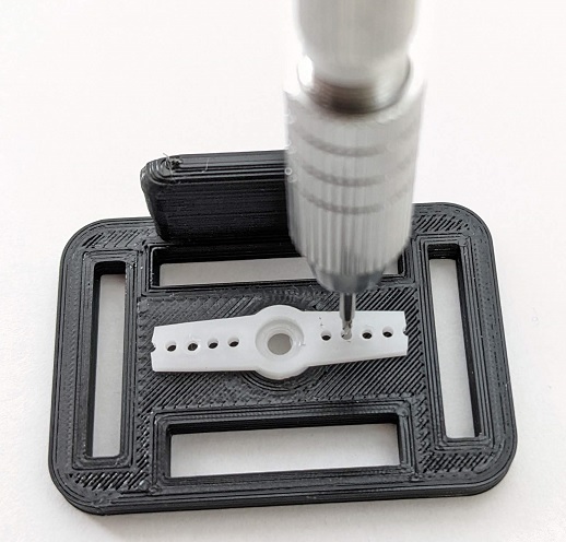
Attach the upper horn to Arm_Shoulder. Secure with M1.4 tapping screws. Drilling a pilot hole with a 1 mm drill will make it easier for screws to enter.
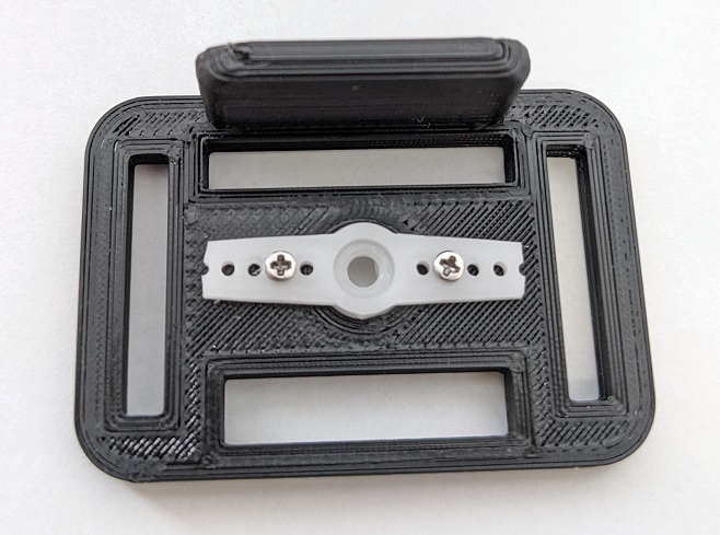
Secure the two places with M1.4 tapping screws.
Servo horn installation 2
Attach the one-winged horn that came with the servo to Joint_Servo_A.
As with Installation 1, make a pilot hole with a 1 mm drill first to make it easier for screws to enter.
Fasten with M1.4 tapping screws.
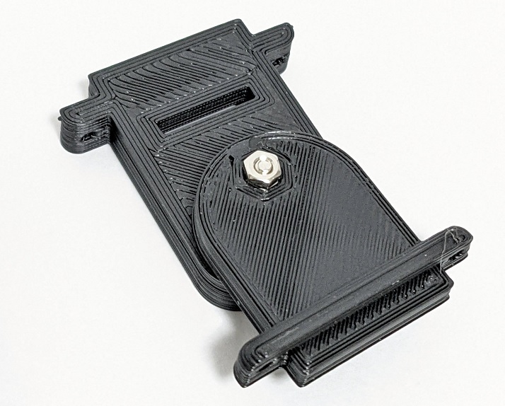
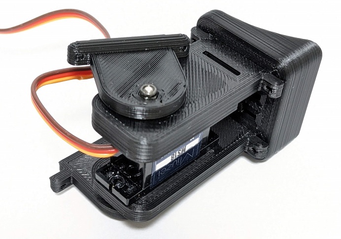
Servo Bracket
* Except for some parts, the photos of the legs are used. The arm parts are a little long.
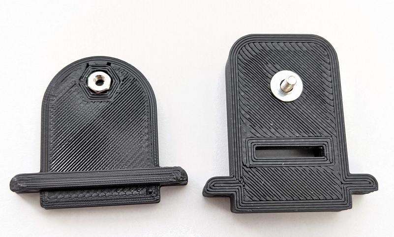
Insert the M2 nut or M2 locknut in the left part (Joint_Servo_B).
Pass the M2x8mm countersunk screw from the back through the right part and cover it with a washer. (The photo is for MS18)
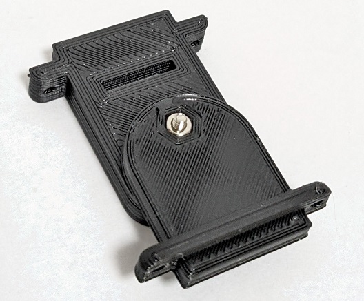
Align the two parts and tighten from behind. * There is a washer between the parts.
Tighten it once and loosen it slightly enough to move the two parts.
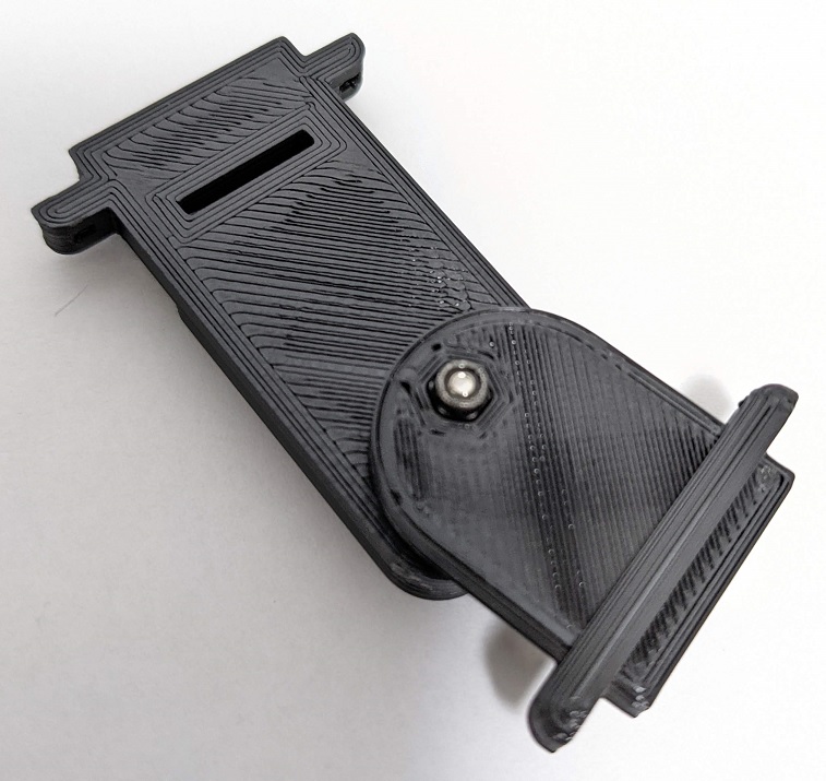 The photo is for M2 locknut.
If it is not a locknut, you can cover it with an M2 nut to make it a double nut. It will not come off easily.
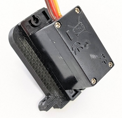
Attach Leg_Bracket_A to the servo.
If it is unstable, fix it with the screw attached to the servo.
Install the parts assembled above (Leg_Blacket_B and Joint_Servo_B).
Installation of servo and servo horn
Import setup code
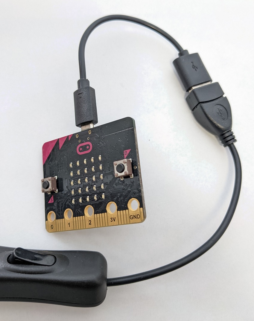
Import the setup code “microbit-ForSetUp.hex” into the Micro:bit.
You can use the setup code “microbit-ForSetUp.hex” used on the legs as it is.
Servo and Servo Horn
Attach the arm servo connector to the servo driver board.
Connect to SV8 for the right hand and to SV7 for the left hand.
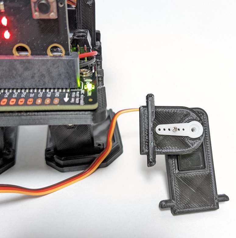
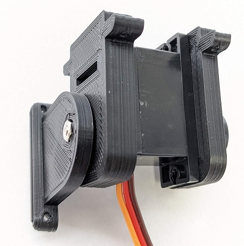
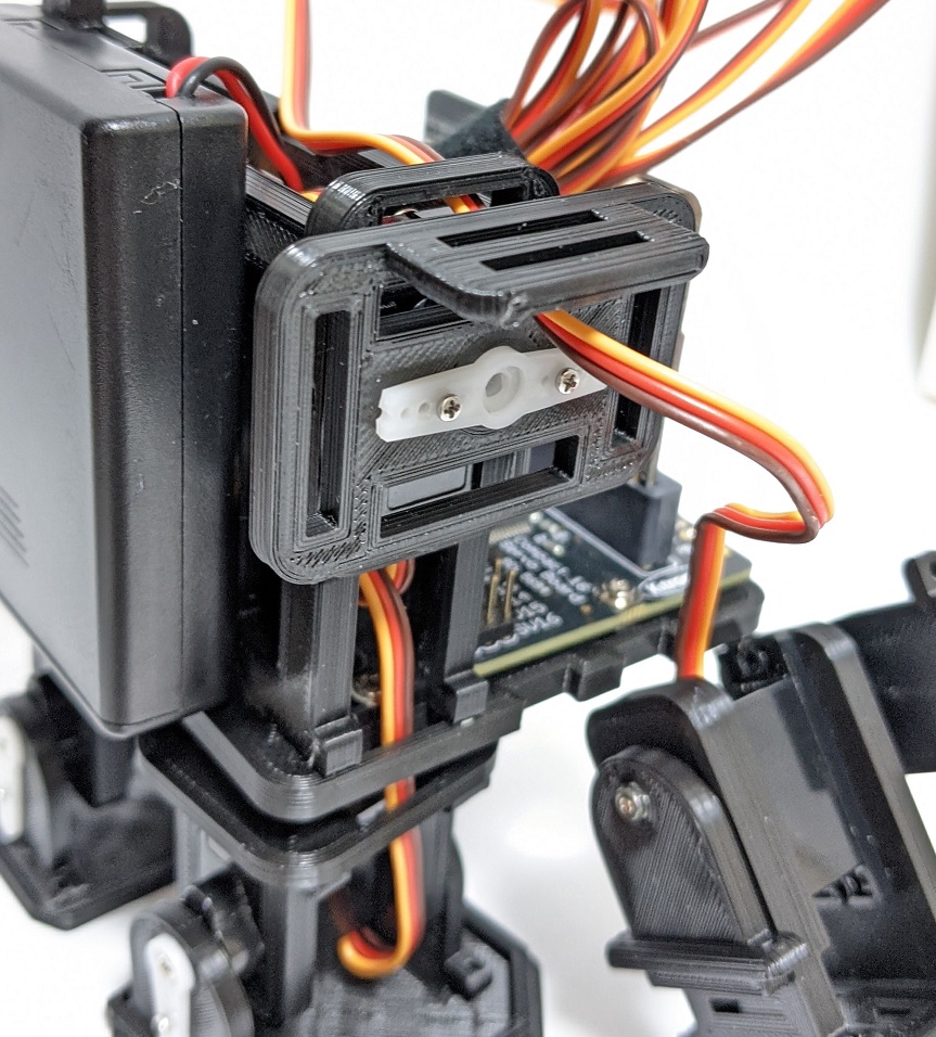
Attach the Micro:bit and align the servo and servo horn parts with the switch on.
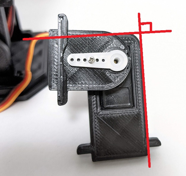
In the case of the arm, attach it as vertically as possible or open it as shown in the picture.
The photo is for the right hand, but be careful of the orientation. The servo horn is on the back side. When creating the left hand, it will be in the opposite direction.
Screw the servo horn with the screws attached to the servo.
Hand
Hand assembly
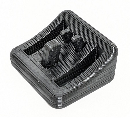
Assemble 4 parts (3 fingers).
Three fingers fit in a small hole.
Assemble the servo part and hands. The hand has an orientation.
If it is unstable, use M1.4 tapping screws in 4 places.
If you make a pilot hole with a 1 mm pin vise, it will be easier for screws to enter.
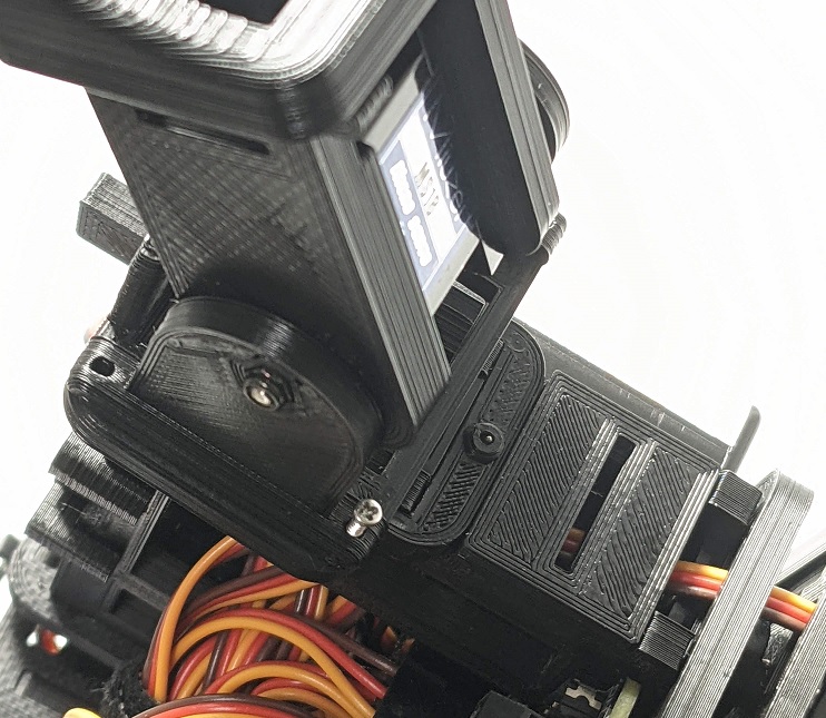
Attach to the body
Remove the servo and servo driver board once.
First, insert the code into the hole in Arm_Shoulder.
Connect the servo and servo driver board again.
Turn on the power and fix the body and Arm_Shoulder. The body and Arm_Shoulder should be as straight (vertical) as possible.
Secure with the screws attached to the servo.
Connect the body and arm, and if it is unstable, fix it with M1.4 tapping screws.
If you make a pilot hole with a 1 mm drill, it will be easier for screws to enter.
Connection of both arms
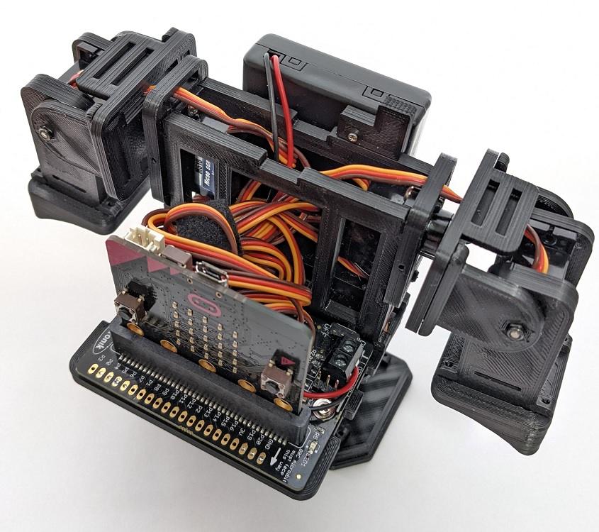
Assemble in the same way and attach both arms.
Take out the connector from the hole in the center of the body and connect it to SV7 and SV8.
This completes the arm assembly.