
Install 4 servos, servo driver board, and power supply.
Parts
- (x4) Servo(SG90 or MS18)
- Servo driver board
- Battery box
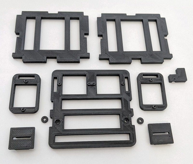
- (x1) Body_Base
- (x2) Body_Vertical
- (x1) Body_ETC
Servo installation
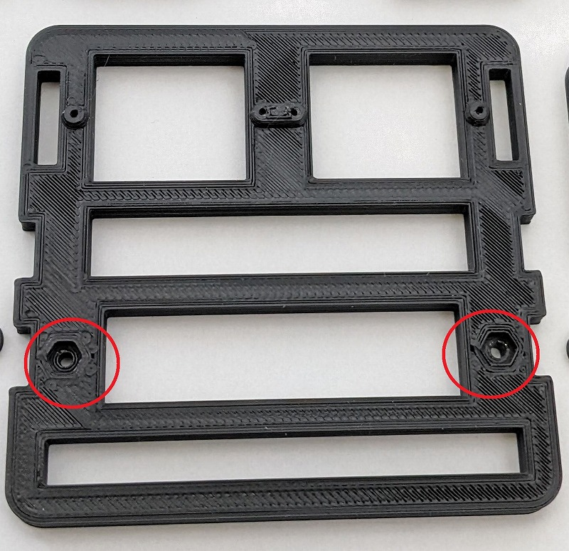
Drilling
This step is not necessary if you can print out with a clean hole.
If the holes in the red circles below are incomplete, clean them with a 2mm pin vise.
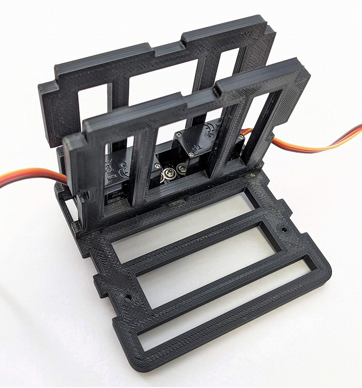
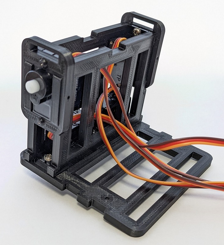
Servo installation 1
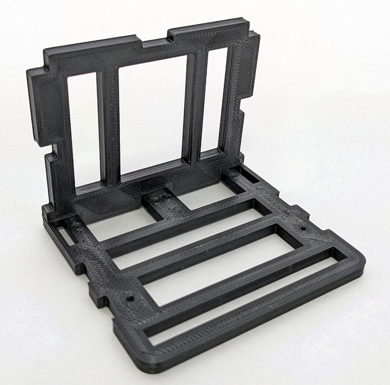
Assemble Base and Virtical.
Base has the bulging side down.
Virtical has no front and back.
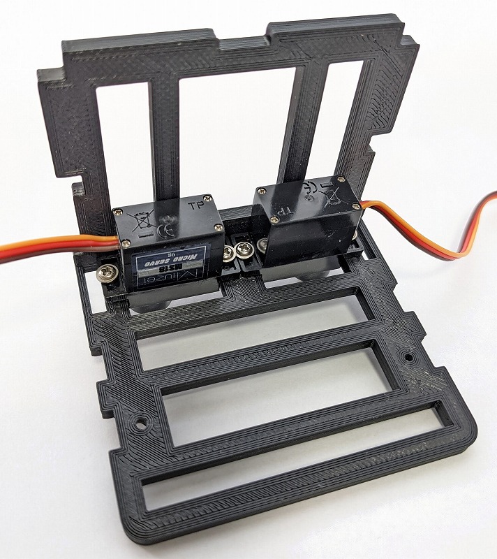
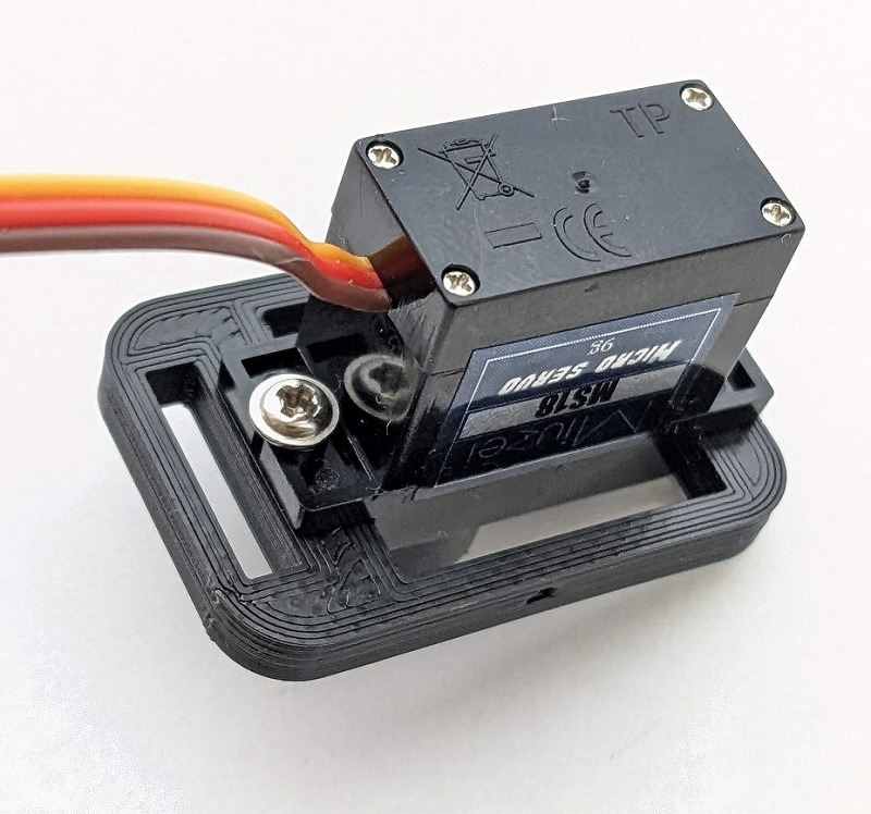
Temporarily fix the two servos in four places with the attached screws.
The photo is for MS18. The same is true for SG90.
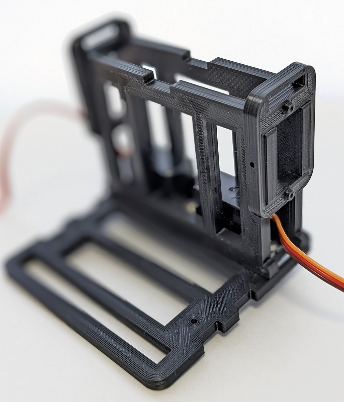
Insert another piece and fully tighten the screws.
Lower.
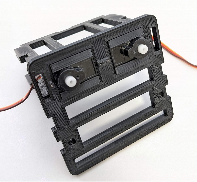
Servo installation 2
temporarily insert the shoulder parts.
Remove the shoulder parts and temporarily fix it to the servo.
Assemble the temporarily fixed servo and body, and check that they fit.
Re-disassemble, fully tighten the servo screws, and assemble.
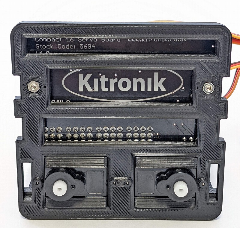
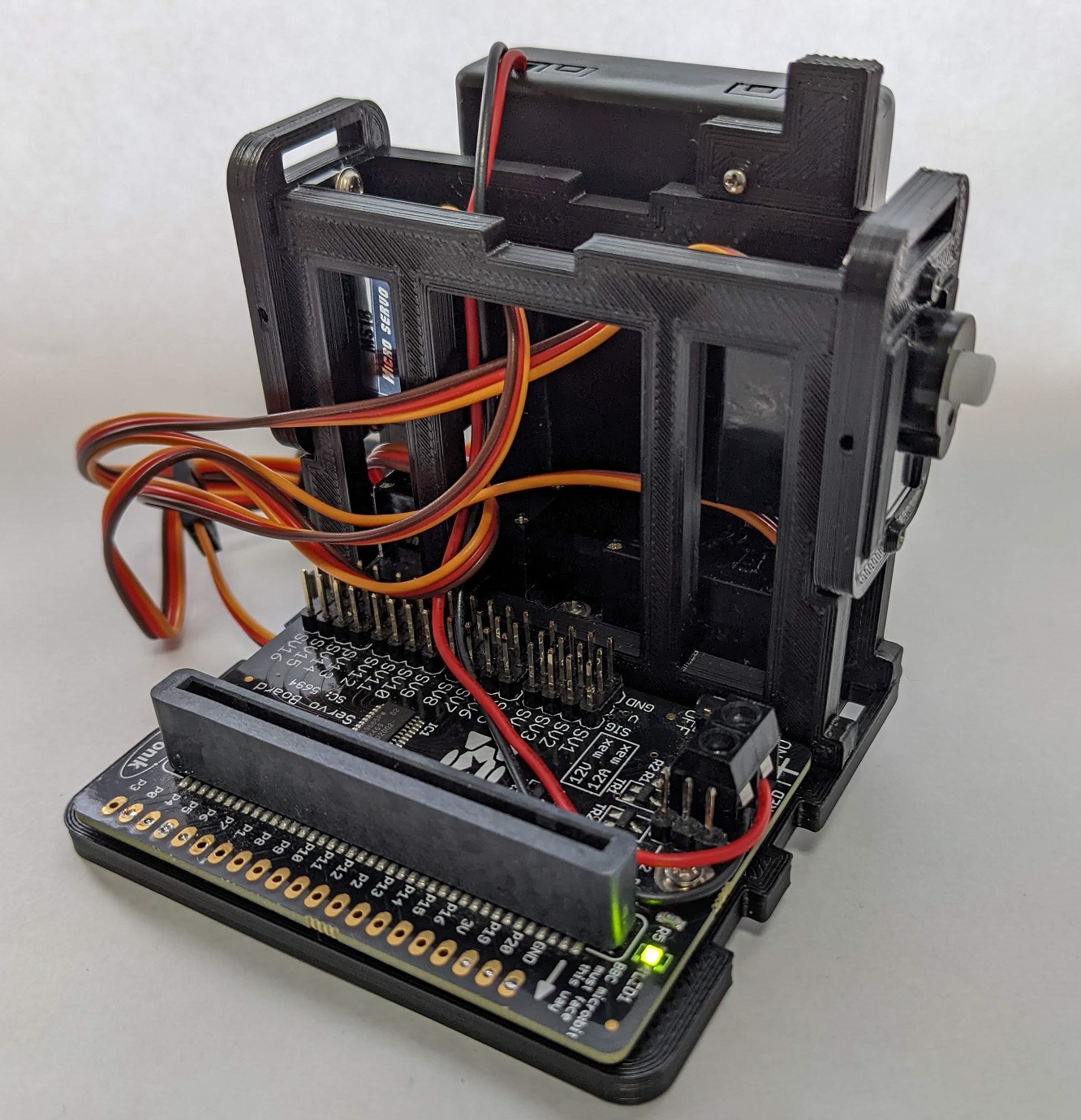
Installation of servo driver board
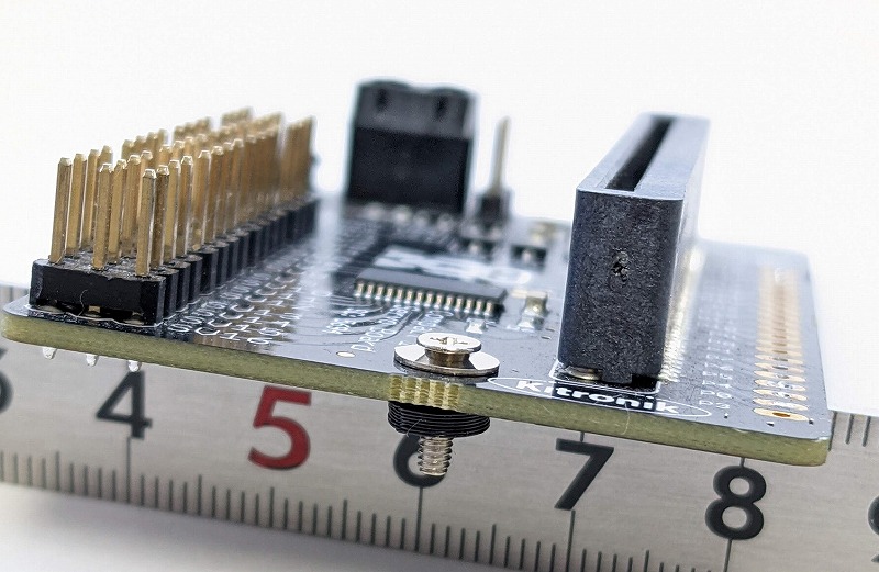
Pass the fixing screw through the servo driver board.
The order is countersunk screw M2x8mm, washer, driver board, printed washer.
Insert a nut on the back and fix it.
Installing the battery box
Fix switch parts
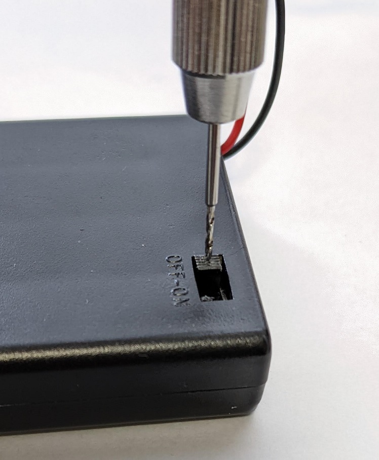
Drill a hole in the switch with a 1mm pin vise.
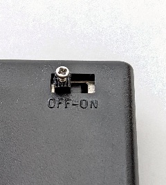
Temporarily install a 1.4 mm tapping screw.
Make sure it can be fixed and remove the screws.
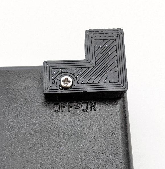
Secure the switch parts with the same screws.
Attach the battery box to the body
Attach double-sided tape to the back.
There is no problem with fixing screws, etc.

Paste the battery box.
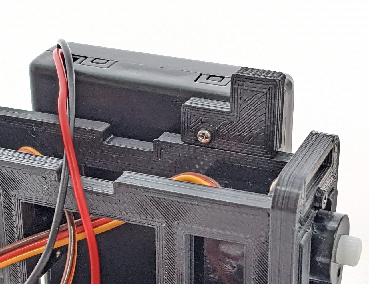
Front.
Connect the power cord
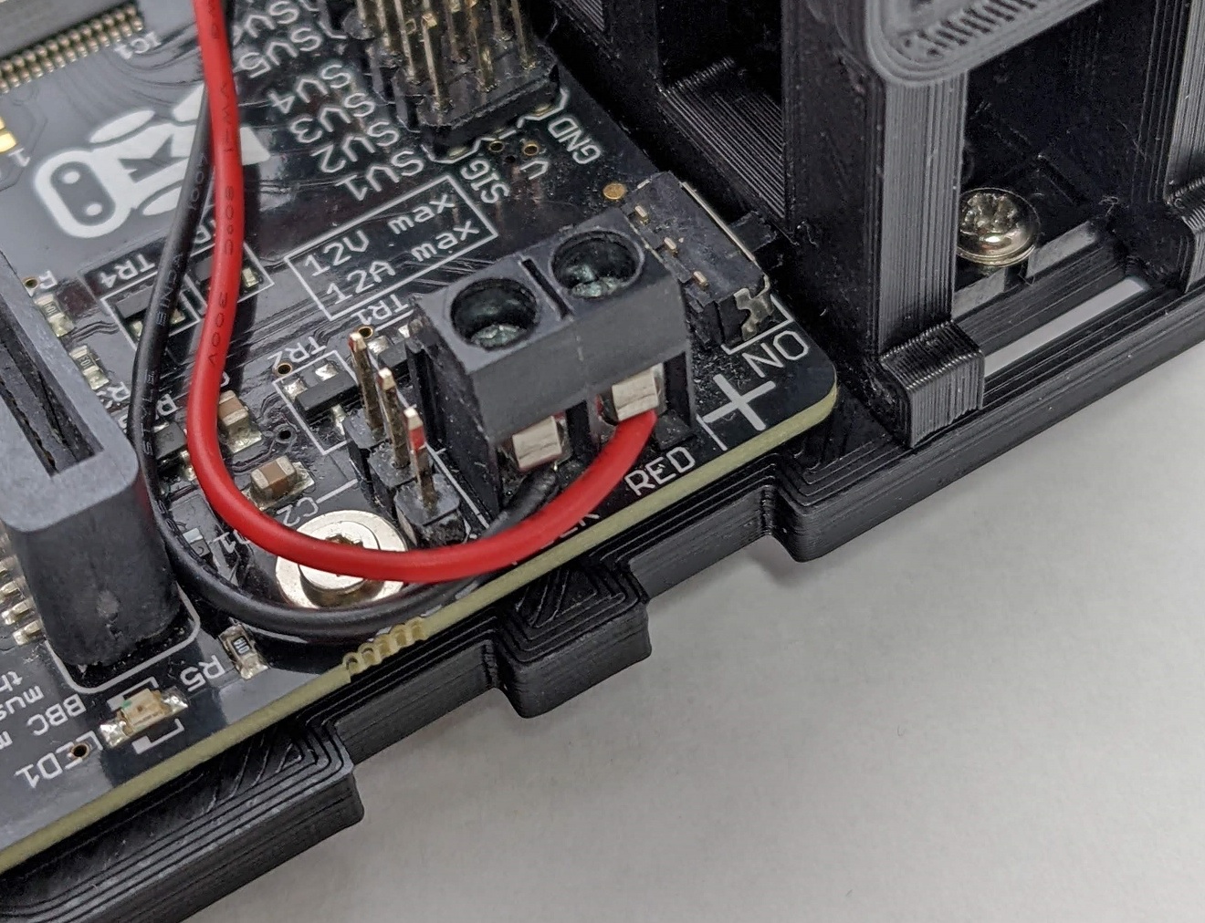
Connect the battery box and driver board.
The driver board is labeled BLK and RED. Connect the black and red cords accordingly and tighten with a screwdriver.
Insert the batteries and slide the switch to the right to make sure the LED on the board lights up.
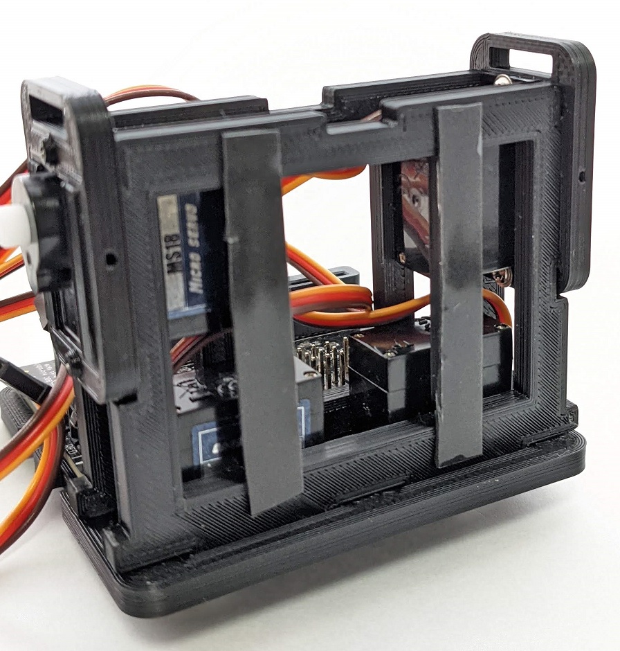
Servo connection
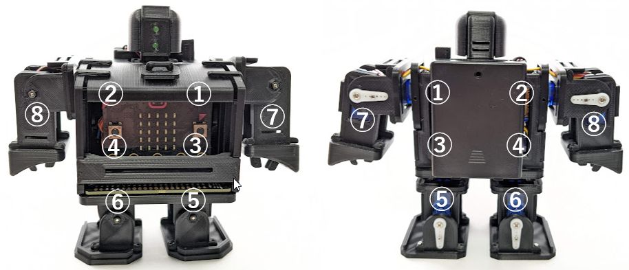
Servo position and number.
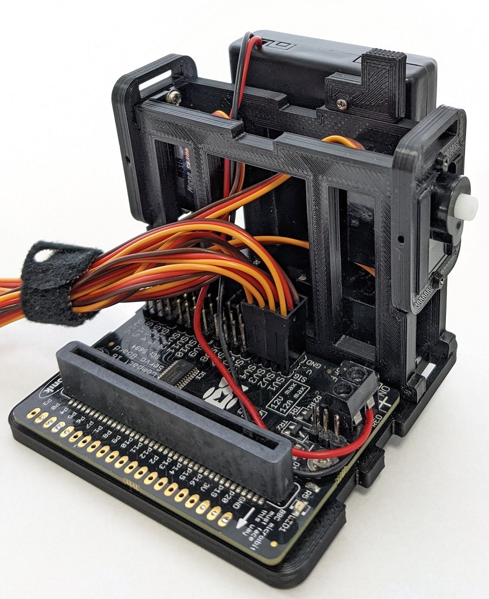
Connect from SV1 to SV4 written on the controller so that the front is the yellow cord and the back is the brown GND. If you make a mistake, the servo may be damaged.
This completes the assembly of the body.