
If you don’t have an LED on your head, just assemble the printout parts.
Parts
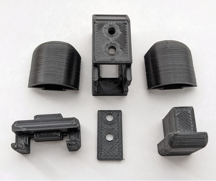
- Head_Middle (upper center)
- Head_Side (upper left and right)
- Head_LED (bottom center)
- Head_Neck (bottom left)
- Head_Back (bottom right)
If you want to attach an LED to your head, also use the following. (Refer to Parts)
- (x2) 3mm LED (with resistor)
- (x1) Universal board
- (x3) Jumper wire female x female 10cm~
- (x3) Right angle pin header
LED preparation
Drilling
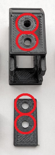 This step is not necessary if you can print out with a clean hole.
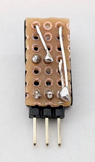
If the holes in the red circles below are incomplete, clean them with a 3mm pin vise.
Soldering and cutting the board
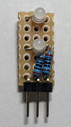
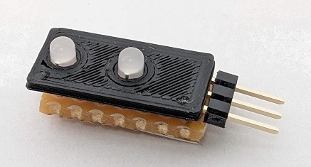
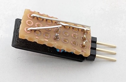
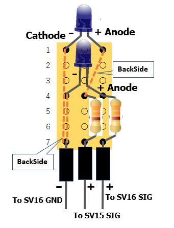
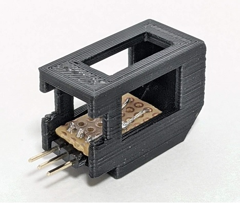
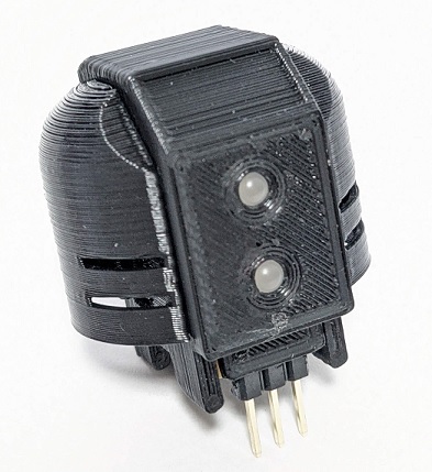
Install the LED, resistor, and pin header from the front as shown in the schematic.
It is easier to work with the Head_LED print parts.
In the photo on the left, it is soldered in 5 places.
LED test
Once connected to the main unit, test the LED.
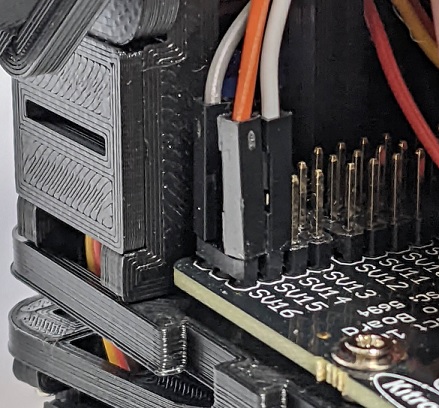
Connect to SV15 SIG, SV16 SIG and GND.
For the LED test, you can use the setup code “microbit-ForSetUp.hex” used on the legs as it is.
The brightness of the upper and lower LEDs changes with the A and B buttons on the Micro:bit main unit.
Head attachment
Assembling the head
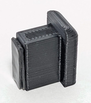
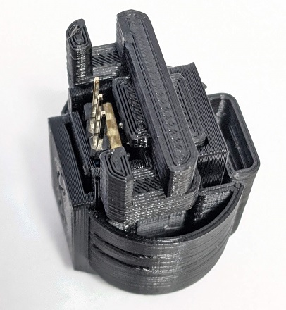
Install the LED inside “Head_Middle”.
Paste something that will be a cushion on Head_Back.
In the photo, two double-sided tapes are attached.
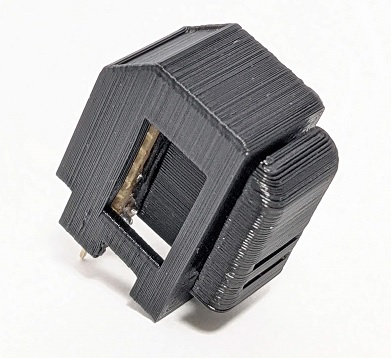
Insert Head_Back from behind Head_Middle to stabilize the LED parts.
Fit Head_Side to Head_Middle.
Fit the Head_Neck from the bottom.
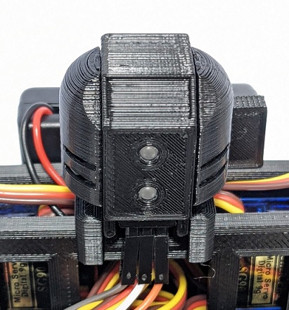
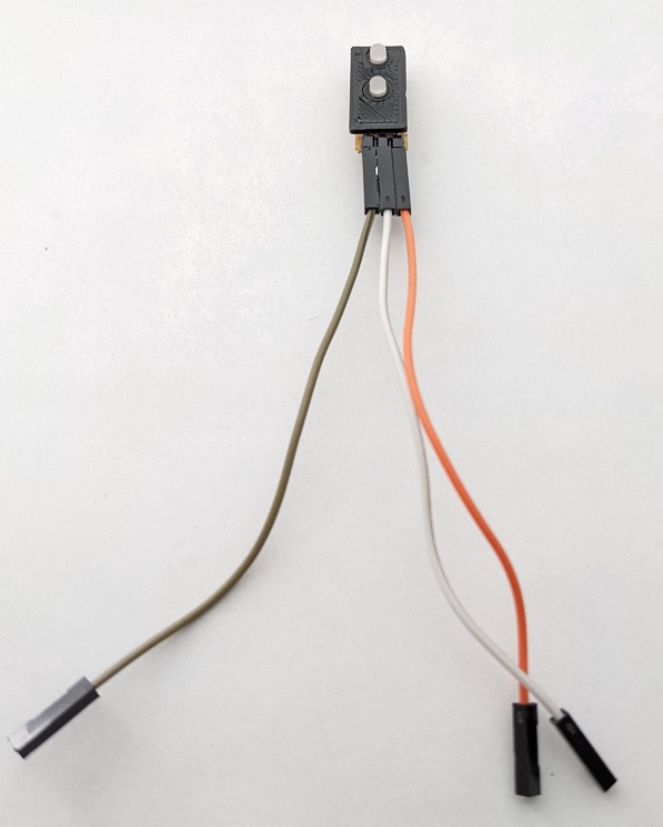
Attach a jumper wire to the head and attach it to the Body.
Connect the connector to SV15 SIG, SV16 SIG and GND.
This completes the head.